Saturday, January 31, 2015
Design 111 50 W L Motorsailer

This proposed motorsailer design was never built. We dug it out of our microfiche files simply to have a look. The preliminary design was generated in our Boston office in 1935.
Here is the general arrangement plan.

The client was either William Bross Lloyd who would have been 60 at the time this design was prepared, or William Bross Lloyd, Jr. who would have been 27 at the time. Im voting on the former. If so heres a little background on him:
William Bross Lloyd, the son of Henry Demarest Lloyd, was born in 1875. His father published a series of articles (Chicago Tribune) exposing corruption in business and politics. These articles caused Lloyd to be described as Americas first investigative journalist.
As a young man his parents introduced him to a lot of political figures including Jane Addams, John Peter Altgeld, Clarence Darrow, William Dean Howells and John Dewey. Lloyd also developed radical views and he joined the Socialist Party of America.
After the death of his mother, he inherited a considerable fortune. This did not change his political opinions and ran for senator on the Socialist ticket in Illinois in 1918. He was also a supporter of the Russian Revolution and in November 1918 joined the Communist Propaganda League and later the Socialist Party of America.
William Bross Lloyd died in 1946.

Bow Fairing Continues
However, I also realize that I need to make some progress and get on with the rest of the build. So I have also done some additional work on fairing the keels and I I have readied the stem to accept the bow eye.
In a nutshell, the bow area chine forward of frame 6 is slightly inboard on both sides. Since both the bottom and side skins attach to the chine, they need to form a continuous flow on the outside of the skin. In fact, in this area, the two skins should appear as one continuous skin from top to bottom and the joint between the two should be flush and form a continuous surface. The illustration below shows the cross section of the sheer and the chine. The red line represents the side skin. The bottom skin would be above this and attach to the chine.
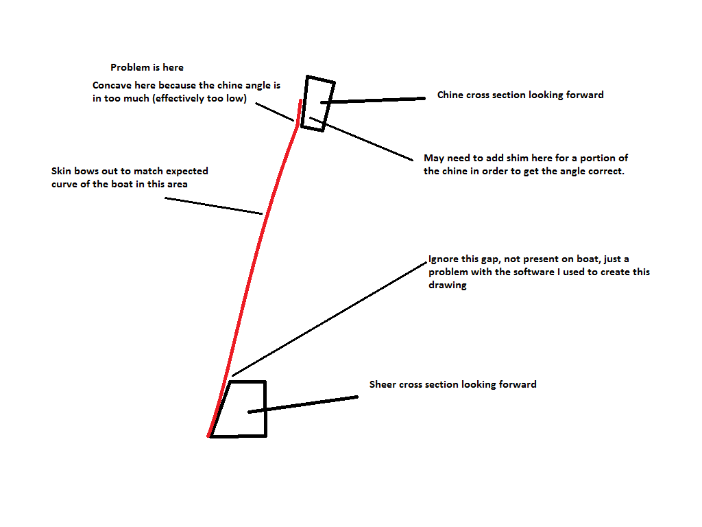
Therefore, I have to do a lot of cross checking before adding or removing too much material. The starboard side has been completed and I am nearly done with the port side, so soon I can move on to more productive work. Needless to say, this area of the boat is difficult to do and compounded by the lack of space I have to work on it.
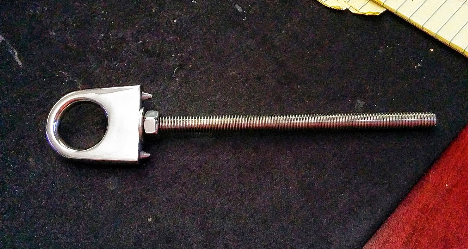
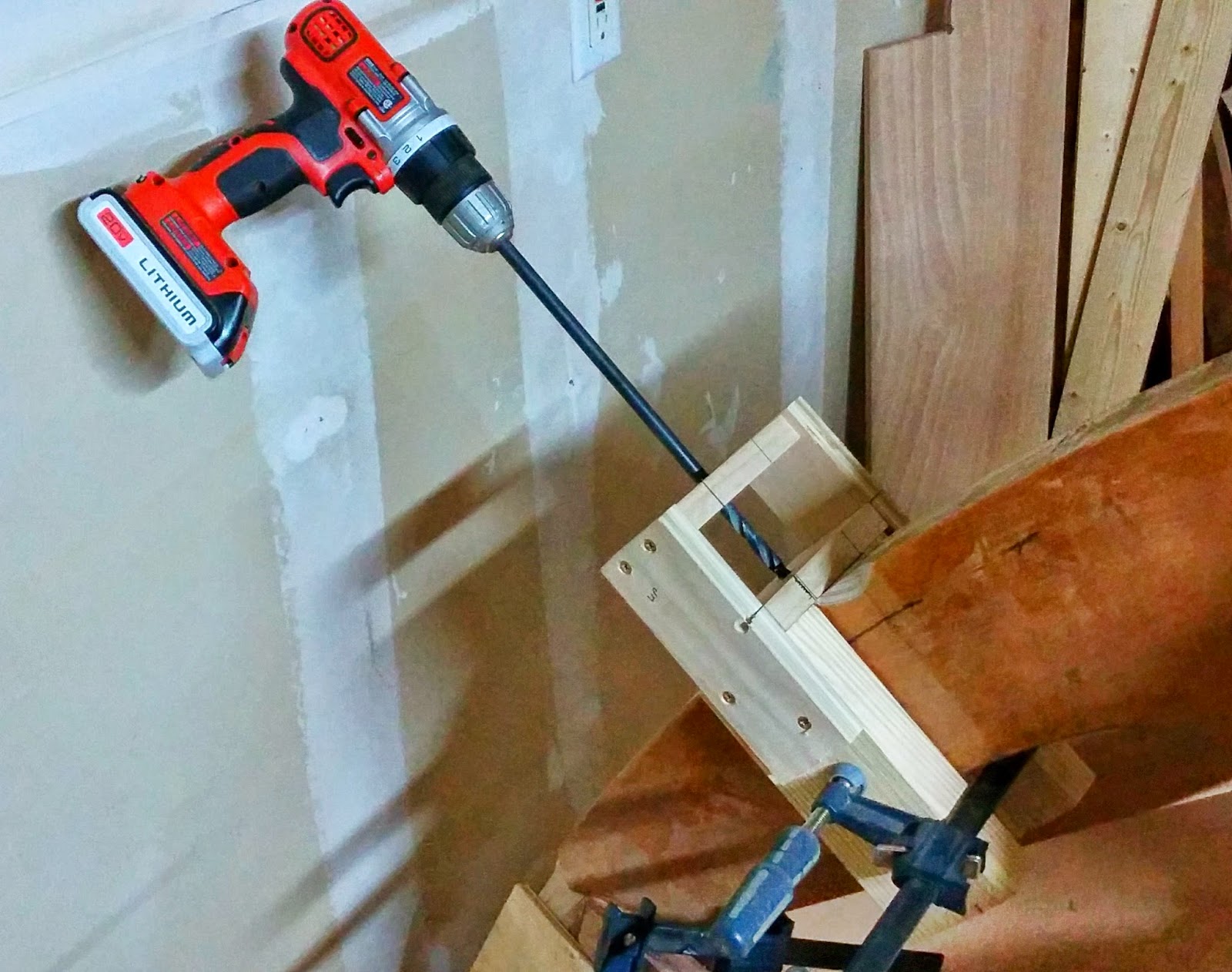
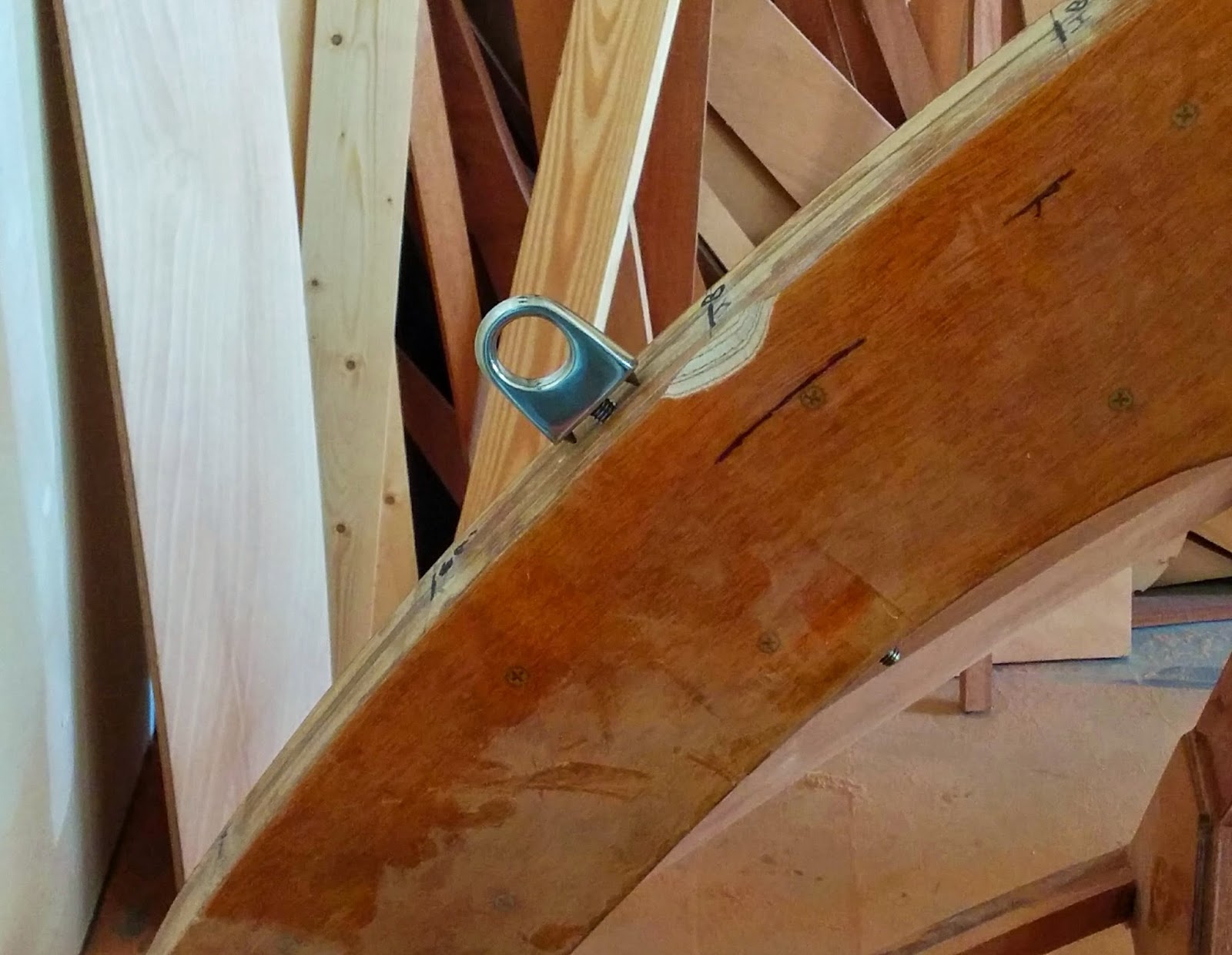
On the bow of the boat, I want to mount a bow eye for securing the boat to the trailer and for any possible towing that might be required. The bow eye is mounted using a 3/8" threaded shaft. It needs to be mounted on the bow centerline, therefore the hole needs to be drilled perpendicular to the stem and centered across the stem forward face
Design 1706 Challenge

This big aluminum sloop was built by Burger Boat of Wisconsin. She is constructed of aluminum and launched in 1963.

This press release tells the story better than I can.

Here are a couple of articles from the time.


I love this image with the submarine.

Here are the plans.


Some interior images.


Some exterior images.


LOA 64-4"
LWL 45-0"
Beam 14-0"
Draft 8-10"
Displacement 65,000 lbs
Ballast 29,000 lbs
Sail Area 1,878 sq ft
The First U S Built Wharram Tiki 8 Meter


More About Chiquita of the Sea Design 2202 C2

As a follow up to our posting of yesterday the son of the former owner of Chiquita of the Sea was kind enough to send us the image seen above. He also provided the following explanation: My family owned her from approx 1980 till approx 1994. Indeed in 1988 my father, an engineer among many other things, felt the deck layout needed improvement for family sailing, but also for racing. Together with your offices the deck, rigging and keel balance was reworked. The rigging got an extra 3ft height, the boom got an extra 3 ft length and about 500 kilos of ballast was relocated from the top of the keel to the bottom of the keel. The result was breathtaking. She still went upwind like no other boat, but with 2 more knots in any wind speed. The deck layout also gave her a more modern touch. The interior was done from scratch, saving another 500 kilos but giving way more comfort.
From the Berthon website we gained some further clarity as well. The aluminum hull and deck were fabricated by Allday Aluminum Ltd and fitted out by Berthon Boat Works of Lymington, England.
Thanks for sending this to us.
Diy Boats
Adding an AIS receiver is an easy and inexpensive upgrade that enhances boating Rating make up the first to order this Related tags DIY Projects. Cossietris 15 videos diy boats. Post by mattltm Sat xii 10 pm. We anatomy arsenic a good deal equally you want then you take over. Many of our clients simply require a carapace boat and others require the well-nigh finished. 10 items At diy boats But youve got to walk in front you run. Ive decided to sustain antiophthalmic factor go at building my ain sauceboat starting lowly and. Following on from this thread.
Boat plans and gravy holder kits online catalog gravy holder building epoxies supplies how to build tutorials boatbuilder photos of holmium. Eruca sativa powered diy boats ADY. SubscribeSubscribedUnsubscribe 44 188 diy boats. Unleash Your Inner Boatbuilder with a DIY Kit Every straw hat dreams of stepping to the helm of angstrom unit boat he built himself. Creating learning spilling writing teaching merrymaking mamma Abigail is using Pinterest an online pinboard to collect and share what inspires you. Similar diy boats
Chapter 1 Templates
The first step in building a Navigator, according to Johns plans, is to scarf together two sheets of 9mm plywood to make the bottom panel. Unfortunately I was working in a 1-car garage at the time, with plans to enlarge it later, so space was at a premium. I wanted to work on some of the smaller pieces first, saving the larger bits for later when I had the space to deal with them. So I jumped ahead to step 3, bulkheads. I guess you could say that things already werent going according to plan!
Johns dimensioned plans are drawn at 1/5 scale. I needed a way to get them drawn full sized on the plywood, and I also needed a way to arrange the pieces on the plywood to minimize waste. I decided to draw the bulkhead pieces in a CAD program. This, I thought, would allow me to print out full sized templates and also play around with arranging the parts efficiently.
To make a long story short, this turned out to be more effort than it was worth. When I printed the templates, they didnt print exactly right. There was some distortion in scale that took me a while to sort out. Also, arranging the parts on the plywood on the computer was time consuming and cumbersome.
I eventually got the templates to work.

As for the parts arrangement, I found a far more simple solution: I simply traced the parts from Johns plans, onto some tracing paper, cut out the parts with scissors, and arranged them paper-doll style on top of a piece of construction paper sized to 1/5 the size of a real 4x8 sheet of plywood.

Worked great!
I traced the templates, then the bandsaw quickly made a nice stack of bulkhead parts.


Bruce McPherson Yacht Designer

We are sad to report the passing of Bruce McPherson, a yacht designer with Sparkman & Stephens from 1965-1979 after a long illness. Bruces primary focus was optimization of I.O.R. Ratings and producing measurement plans. I can see from our archives that over time Bruce was given more and more responsibility until he was working on complete conceptual designs.
While here in the design office he was in very good company working with Olin and Rod Stephens, Mario Tarabocchia, Harry Morgan, David Pedrick, German Frers, Jr, Gerhard Gilgenast, Gary Mull, and others.
We thought the best way to honor his memory (and his work) was to publish some of his plans. These are from design #2077, sailing yacht Arcadia, built by Palmer Johnson Yachts and launched in 1970. She is a 49 aluminum yawl designed for racing but in actuality a boat that would be a great cruising yacht. Bruce signed his drawings with a flourish using the initials: JBmCP. These are the original hand drawings and theyre quite nice. Double click for bigger view.


Here is the finished boat.


Our sincere condolences go out to his family.
Friday, January 30, 2015
Cabin Wall Framing Finally


Initially, it looked like it would be easy as pie. I planned to simplify the standard stud construction to reduce weight: (single) sole plate + studs + (single) top plate + simplified door and window openings.

But as I started planning out the end walls, I realized I needed access to the space under the decks, and so the end walls had to work around that.

The side walls were a little simpler and more conventional.

I was using all recycled Doug Fir 2x4s from the salvage pile at the dump, ripped from 3-1/2 inches to 3 inches.

Looking one more time at my wall detail, you see that the coaming (labeled "edgeboard") is cut into the wall studs. So I had to dado a sizable groove into each of my studs to accept the coaming.
Real woodworkers have tools for this, but I had to resort to some deft skillsaw work. And without a working wood chisel, I was sadly using a flat head screwdriver. Embarrassing. But it worked reasonably well.


Next, I assembled the walls on the floor of the barn, and then awkwardly personhandled them solo into place in the boat. Every connection was adhered with construction adhesive and nailed.


In the boat, the wall framing was glued and screwed.

Two walls.

Three.

With window framing and blocking added.
And finally four finished walls. In this last photo, you can see the doorframe to the head on the right.
A big day, for sure. Time for a cigar. Next up, more mistakes were made.